-
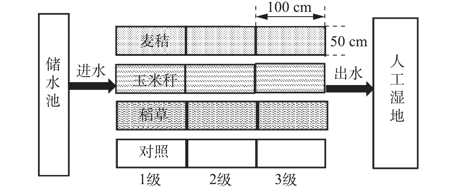
图 1 实验小区示意图
Figure 1. Schematic diagram of test area
-
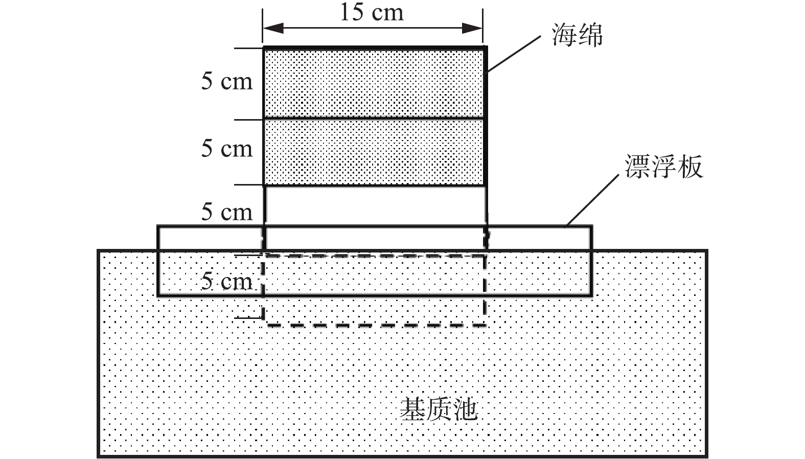
图 2 氨排放通量采集装置
Figure 2. Collection device of ammonia emission flux
-
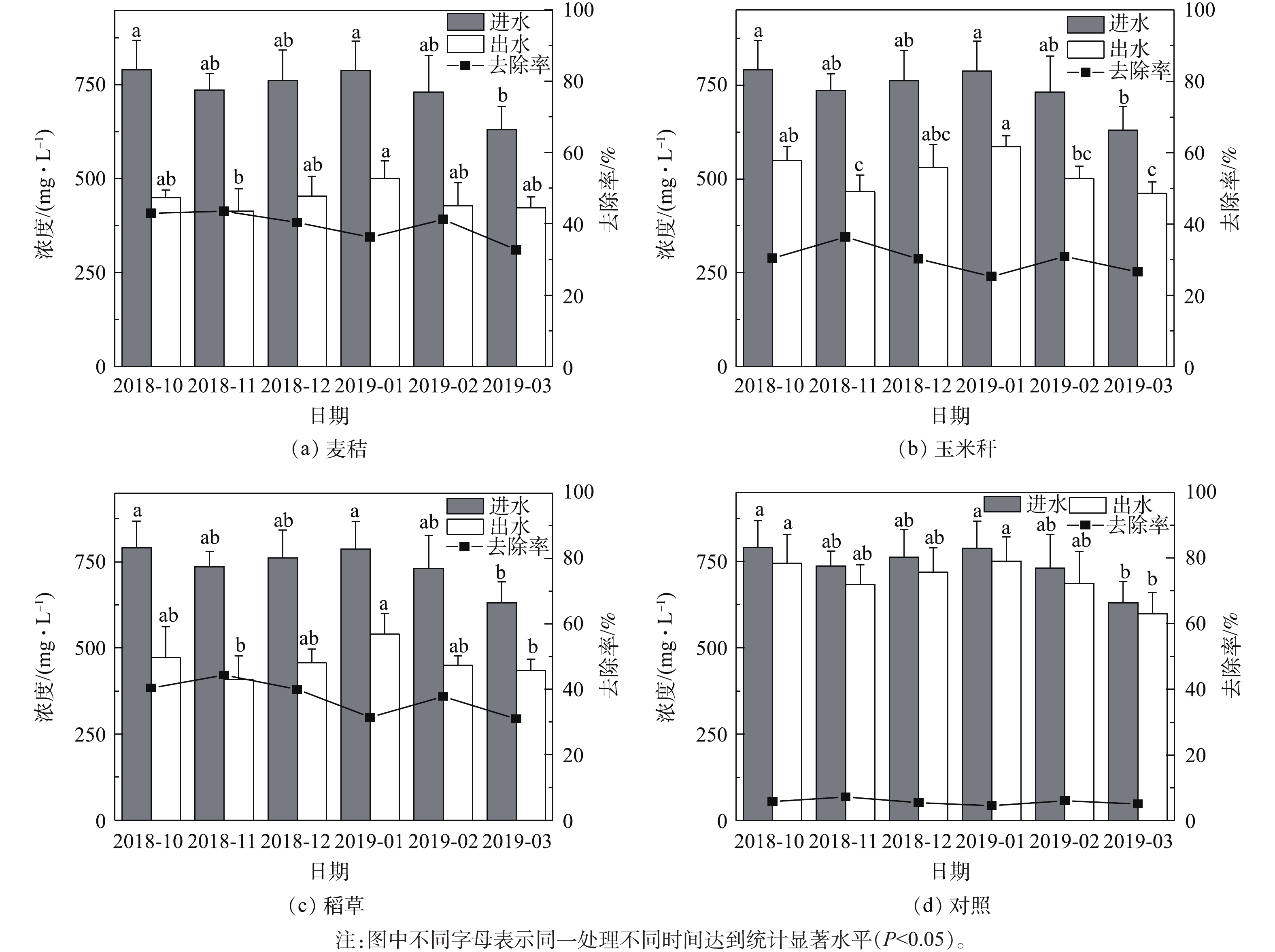
图 3 TN进出水浓度及去除率
Figure 3. Inlet and outlet TN concentration and its removal rate
-
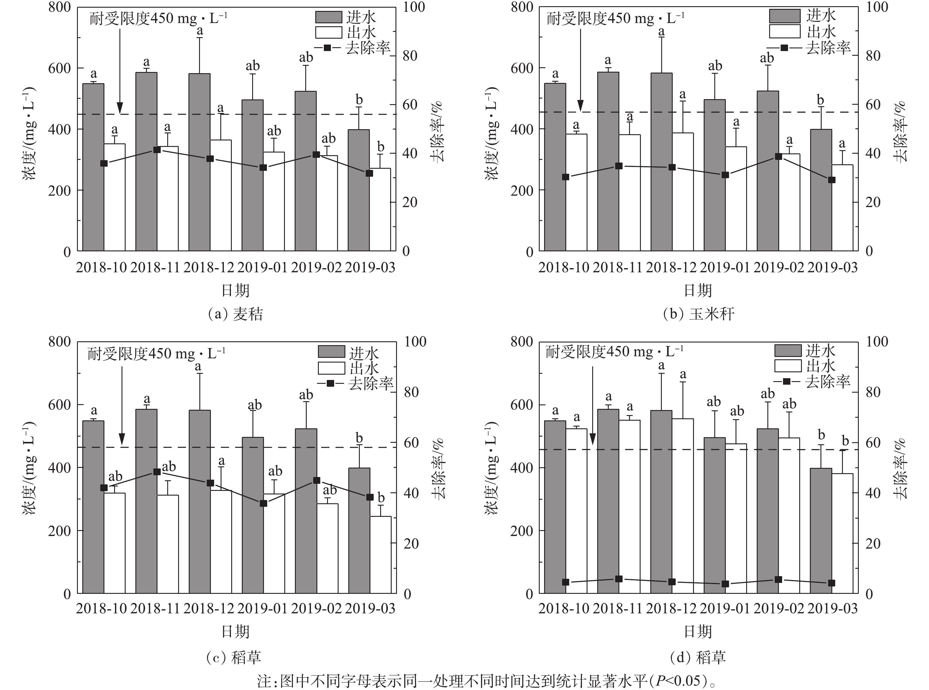
图 4
$ {\rm{NH}}_{\rm{4}}^{\rm{ + }}$ -N进出水浓度及去除率Figure 4. Inlet and outlet
$ {\rm{NH}}_{\rm{4}}^{\rm{ + }}$ -N concentration and its removal rate -
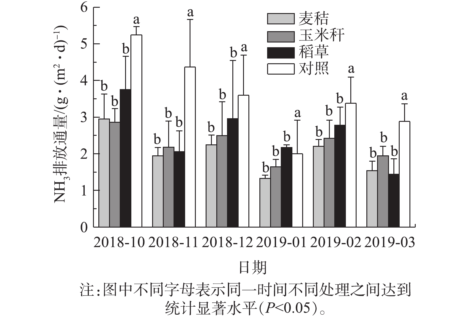
图 5 生物基质材料池氨排放通量
Figure 5. Ammonia discharge flux of biological matrix material tank
-
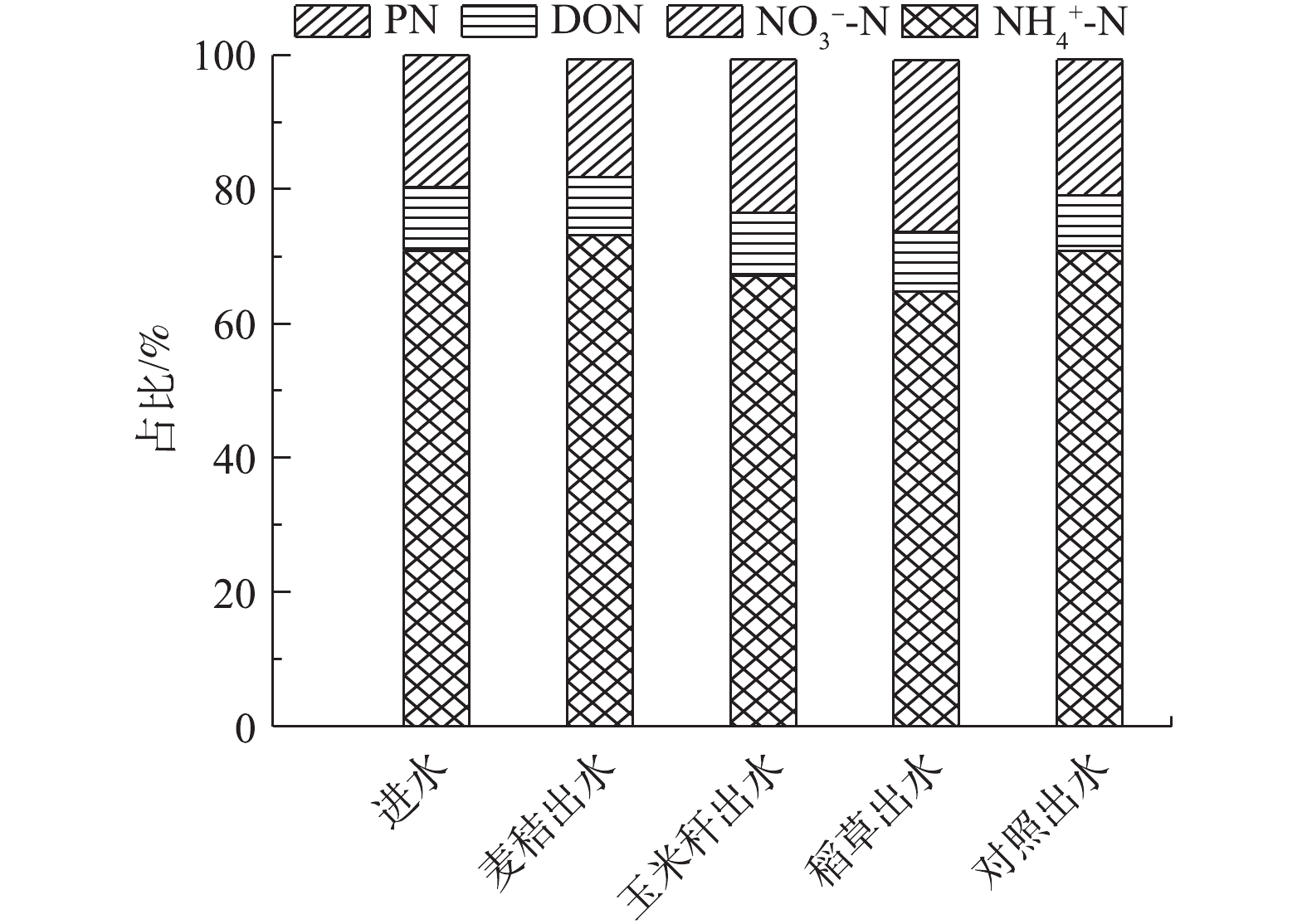
图 6 生物基质材料池进出水不同形态氮素构成的特征
Figure 6. Characteristics of nitrogen composition in the inlet and outlet of biological matrix materials tank
Figure
6 ,Table
2 个