-
-
-
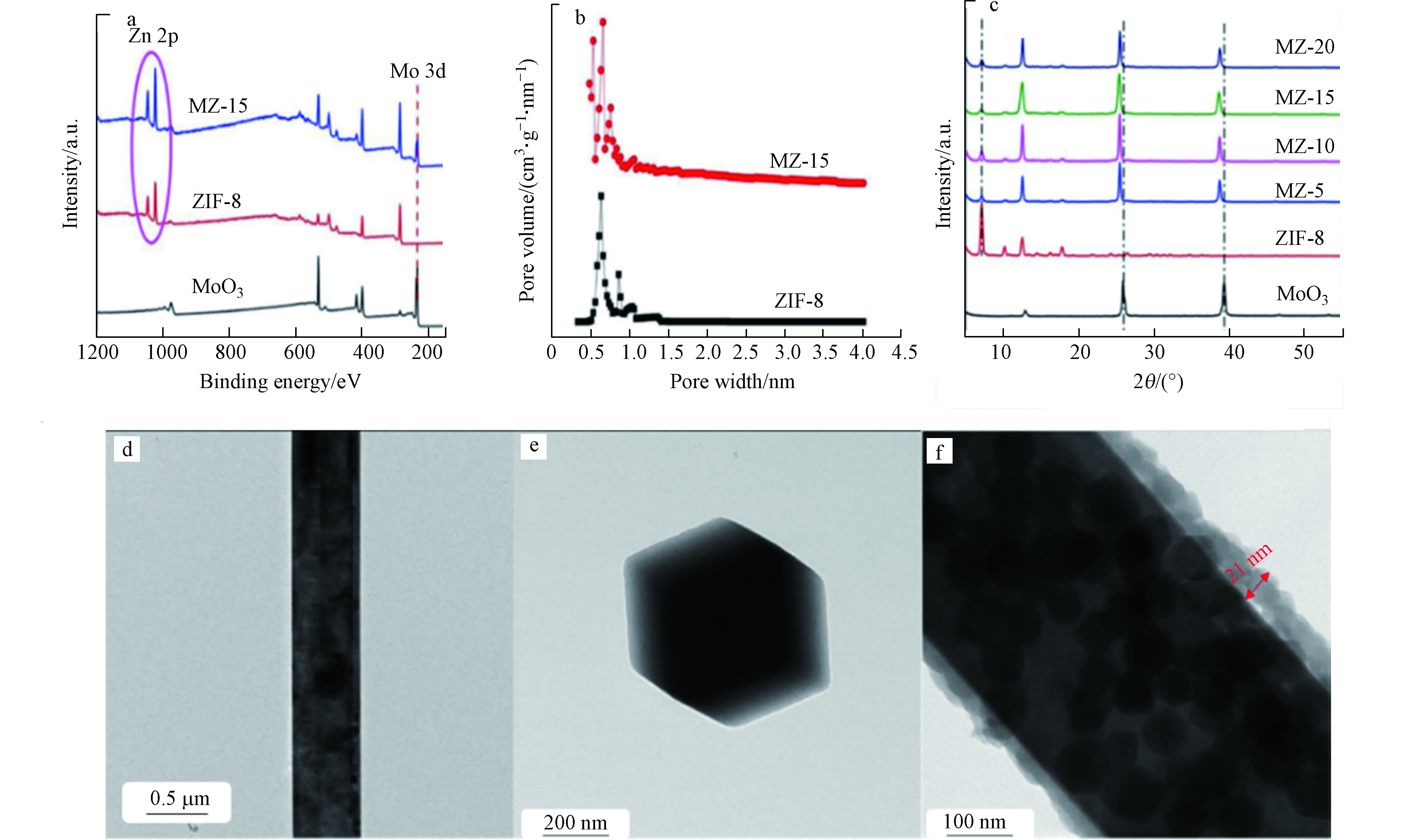
图 3 (a)样品的XPS;(b) ZIF-8和MZ-15的孔径分布;(c)样品的XRD图谱;(d)和(e)为MoO3纳米线和ZIF-8纳米粒子的TEM图像;(f) MoO3@ZIF-8核-壳纳米棒(MZ-15)的TEM图像[41]
Figure 3. (a)XPS of as prepared samples; (b)Pore size distribution of ZIF-8 and MZ-15; (c)XRD patterns of as prepared samples; (d) and (e) TEM images of MoO3 nanowires and ZIF-8 nanoparticles; (f) TEM of MoO3@ZIF-8 core-shell nanorods (MZ-15)[41]
-
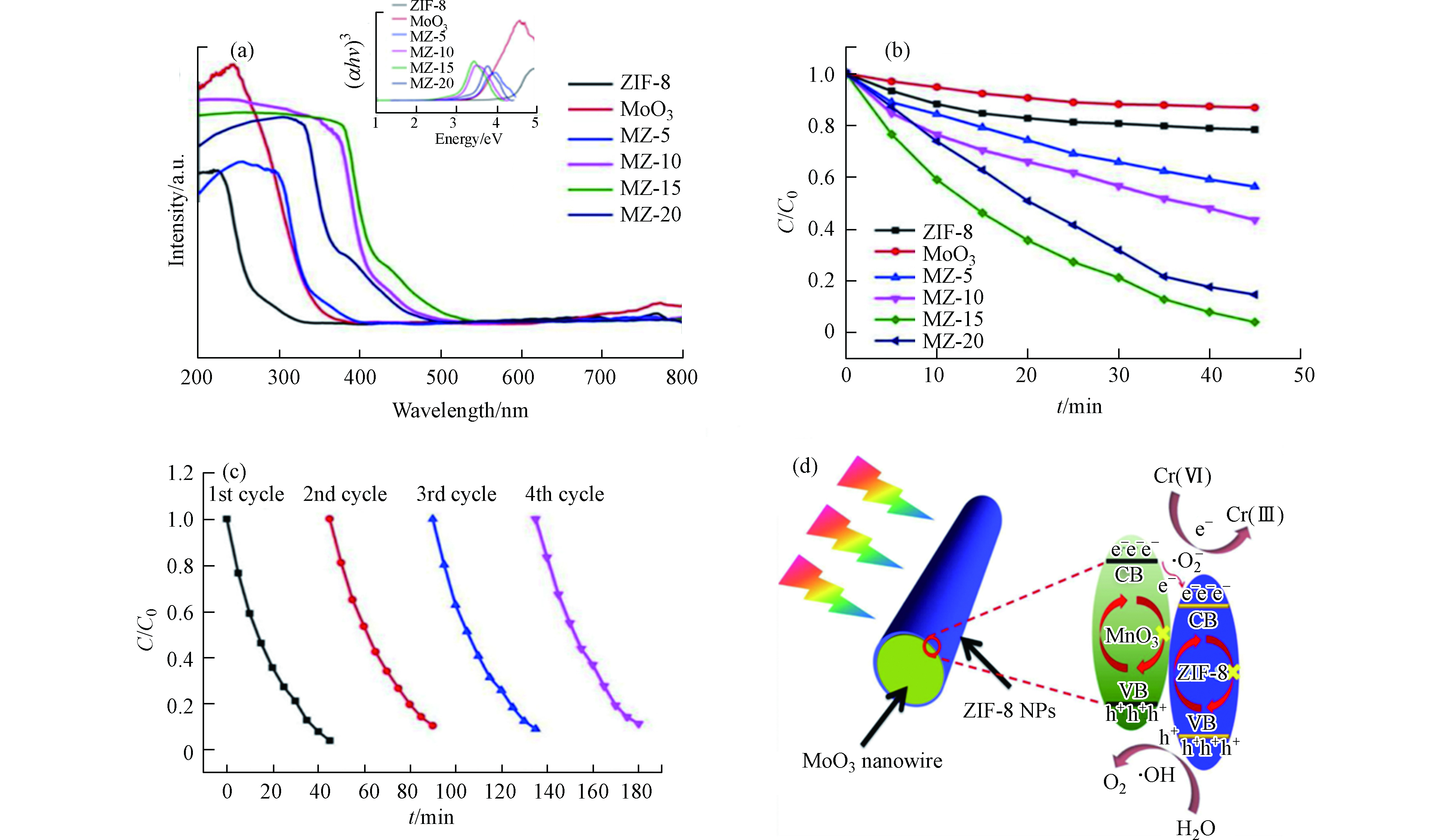
图 4 (a)样品的紫外-可见漫反射谱图,嵌入图显示了样品的带隙值;(b) MZ-15在可见光照射下的光催化性能;(c) MZ-15(50 mg催化剂,100 ml Cr(Ⅵ),20 mg·L−1)的循环实验;(d) Cr(Ⅵ)的还原机理图[41]
Figure 4. (a) UV-vis spectra of samples. The inset figures exhibited the corresponding band gap of samples; (b)Photocatalytic performance of MZ-15 under visible light irradiation; (c)Cycling runs of MZ-15 (50 mg catalyst, 100 ml Cr(Ⅵ), 20 mg·L−1); (d) Schematic illustration of the Cr(Ⅵ) reduction mechanism[41]
-
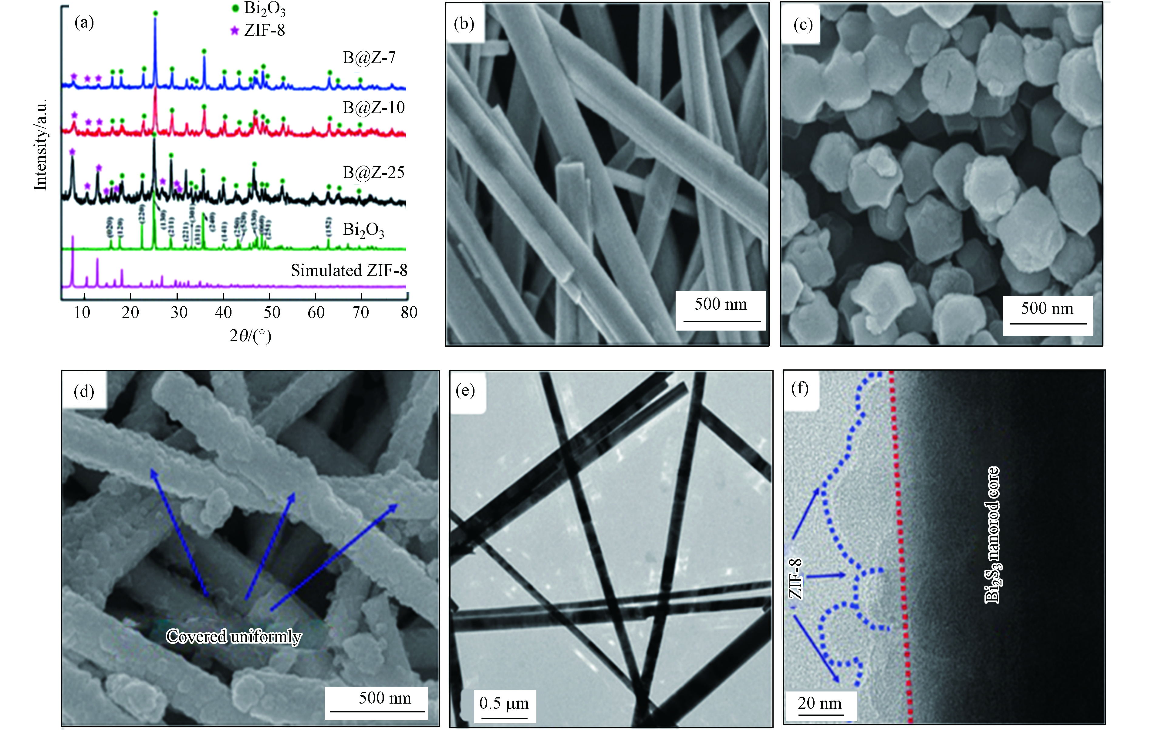
图 5 (a)ZIF-8,B@Z-7,B@Z-10和B@Z-25的XRD图谱; (b) Bi2S3,(c)纯ZIF-8,(d) B@Z-10的SEM图像;(e) Bi2S3的TEM图像,(f) B@Z-10的TEM图像[37]
Figure 5. (a)XRD patterns of ZIF-8, B@Z-7, B@Z-10 and B@Z-25; SEM images of (b) Pristine Bi2S3,(c) Pure ZIF-8, (d) B@Z-10; (e) TEM image of the obtained Bi2S3, (f) TEM images of the B@Z-10[37]
-
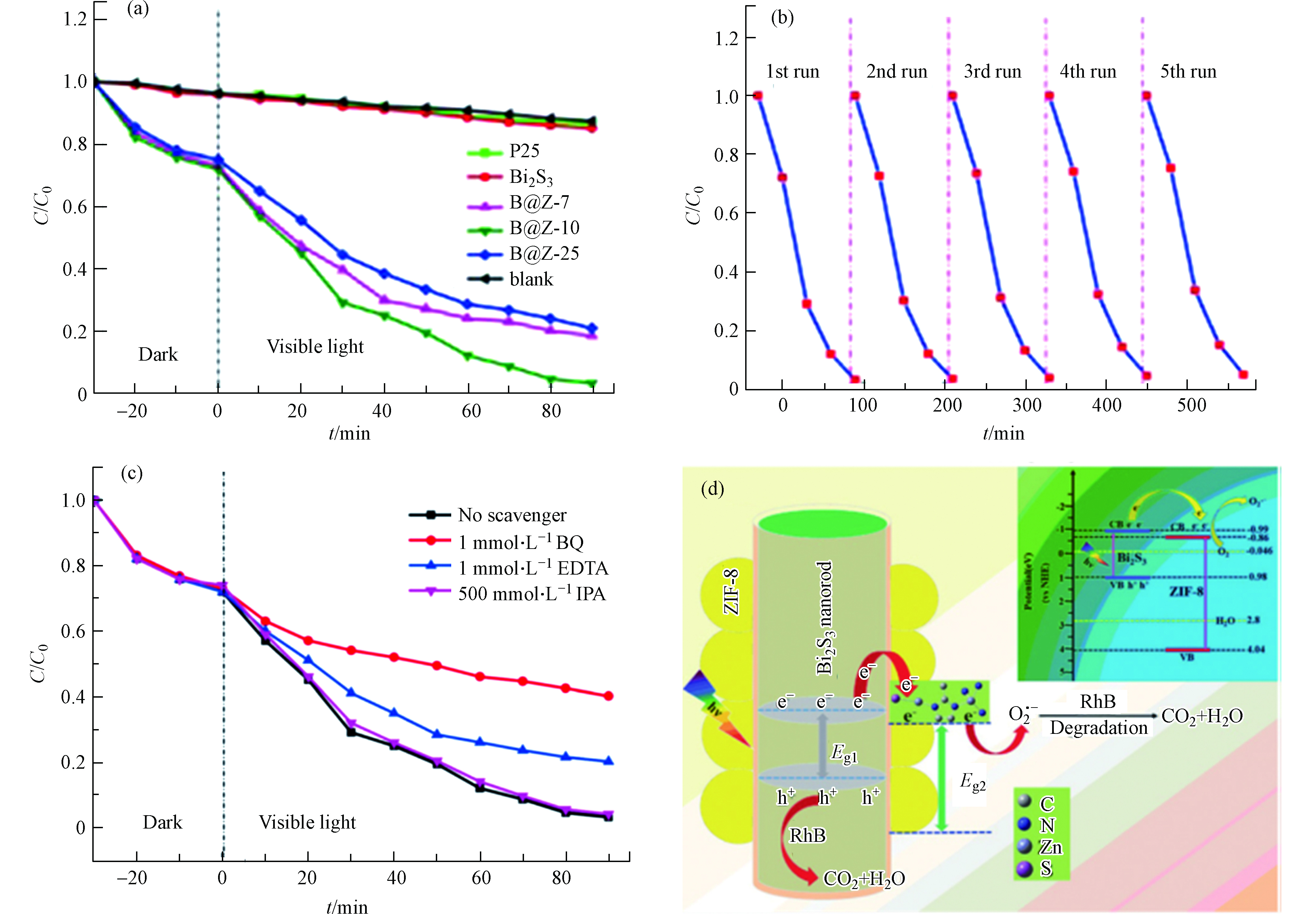
图 6 (a) 不同光催化剂可见光下降解RhB(C0=10 mg·L−1)的效率图;(b)B@Z-10光催化降解RhB循环实验;(c) B@Z-10降解RhB活性物质捕捉;(d) B@Z-10光催化降解RhB的机理简图[37]
Figure 6. (a) Photocatalytic degradation of RhB (C0 =10 mg·L−1) over the samples under visible light irradiation; (b) The cycling of the degradation of RhB in B@Z-10; (c) Effects of different scavengers on RhB degradation in the presence of B@Z-10; (d) A simplified diagram of photocatalytic RhB degradation mechanism of B@Z-10[37]
-
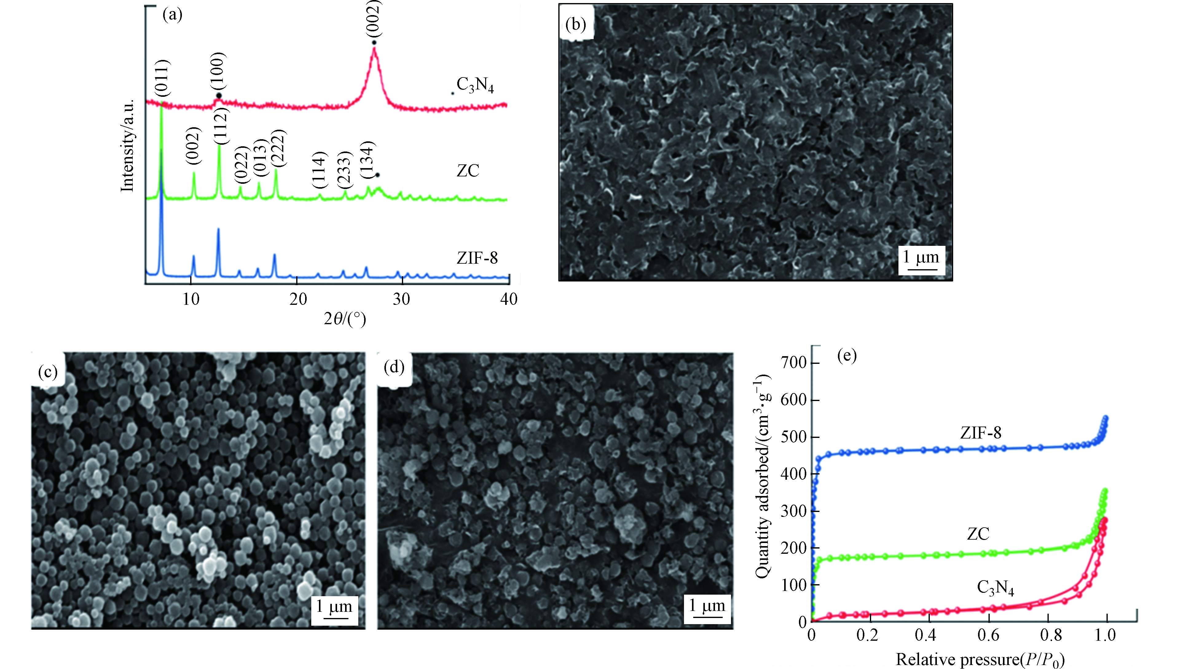
图 7 (a) g-C3N4,ZIF-8和C3N4-ZIF-8 (ZC)复合材料的XRD图谱(标为•的峰表示C3N4相,其余峰均为ZIF-8);(b) g-C3N4,(c) ZIF-8,(d) C3N4-ZIF-8 (ZC)复合材料的SEM图像; (e) g-C3N4,ZIF-8和C3N4-ZIF-8 (ZC)复合材料的N2吸附-脱附等温线[23]
Figure 7. (a)XRD patterns of the as prepared g-C3N4, ZIF-8, and C3N4-ZIF-8 (ZC) composite (Peaks marked • represent C3N4 phases and the remaining peaks are all of ZIF-8); SEM images of (b) g-C3N4, (c) ZIF-8, (d) C3N4-ZIF-8 (ZC) composite; (e)N2 adsorption-desorption isotherms of g-C3N4, ZIF-8, and C3N4-ZIF-8 (ZC) composite[23]
-
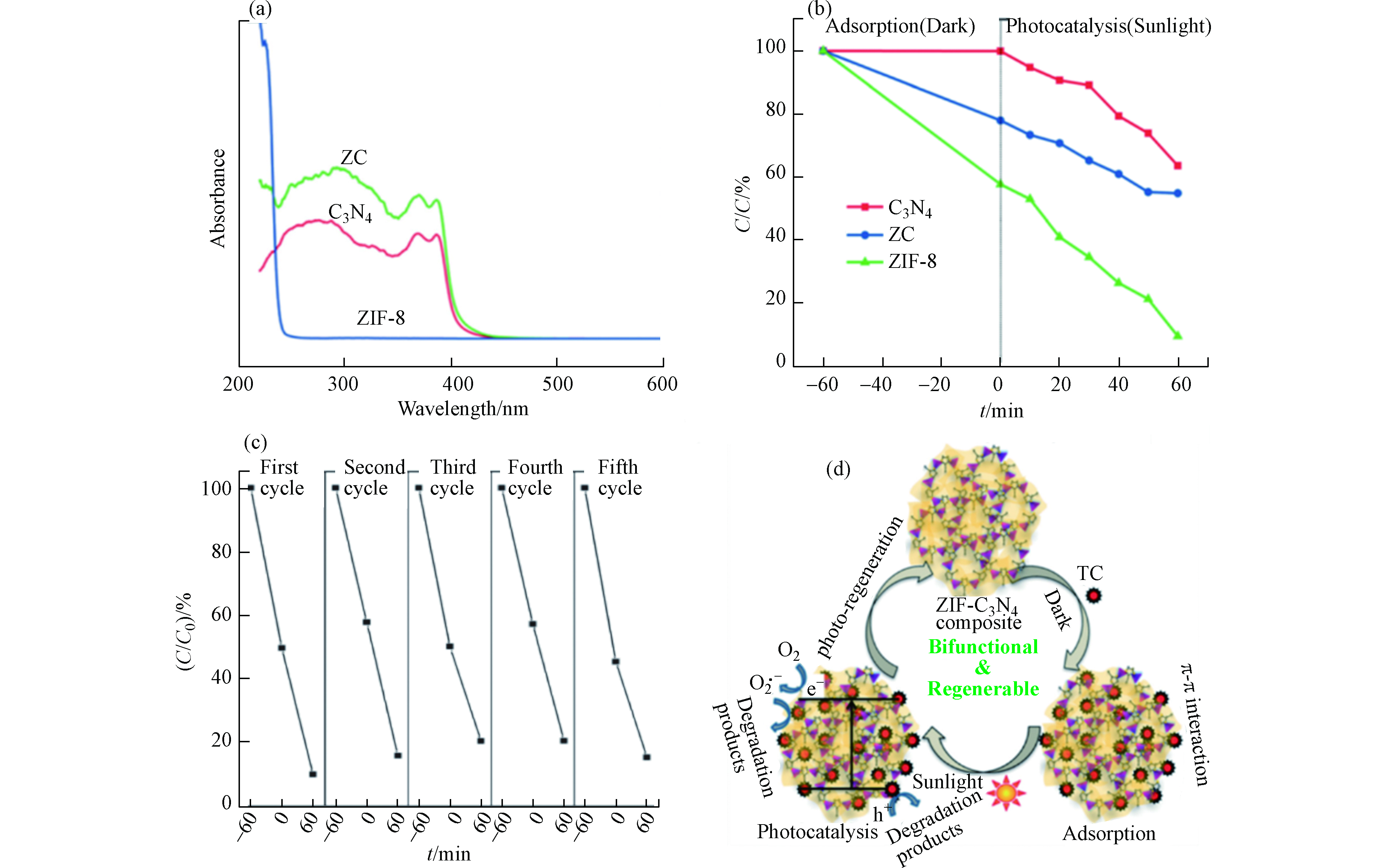
图 8 (a)g-C3N4,ZIF-8和C3N4-ZIF-8 (ZC)复合材料的紫外可见吸收光谱;(b)g-C3N4,ZIF-8和C3N4-ZIF-8 (ZC)复合材料对TC(C0= 200 µmol·L−1)的光催化降解;(c) C3N4-ZIF-8 (ZC)复合材料的吸附与光催化降解的循环实验;(d) C3N4-ZIF-8 (ZC)复合材料对四环素的吸附和光催化降解机理图[23]
Figure 8. (a) UV-vis absorption spectra of g-C3N4, ZIF-8, and C3N4-ZIF-8 (ZC) composite; (b)Photocatalytic degradation profile of TC(C0= 200 µmol·L−1) using g-C3N4, ZIF-8, and C3N4-ZIF-8 (ZC) composite; (c)The repetitive adsorption and photocatalytic degradation cycles of C3N4-ZIF-8 (ZC) composite; (d)Schematic illustrating the adsorption and photocatalytic degradation mechanisms of tetracycline by C3N4-ZIF-8 (ZC) composite[23]
Figure
8 ,Table
2 个