-
含有亚微米/微米级气泡的气-液系统具有传质效率高、吸附性能强和自持时间长的特点[1-2],在化学反应、水体增氧、污水净化、生物医药、矿物浮选和流动减阻等领域具有广泛的用途[3-6]。在多相传质与反应的动态体系中,若气泡被破碎成微米尺度时,其尺寸与形状通过肉眼已无法辨别,其数量也会呈几十、几百甚至上千倍增加,单位体积气泡数量高达109~1011 m−3,气液相界面积可达103~105 m2·m−3(通常的鼓泡塔反应器气液相界面积为102 m2·m−3 量级)[7]。气-液或气-液-固反应一般受界面传质控制,而颗粒与界面将直接决定反应过程的传质速率与表观反应速率。准确测试和掌握微界面体系的颗粒动态特征与变化(微气泡或催化剂颗粒直径、个数、粒径分布、形状和流动状态等)对研究微界面状态下气-液或气-液-固体系的界面传质与反应特性有重要作用。尺度减小的效应导致微气泡臭氧传质速率是普通气泡的1.3~1.5 倍,故可以采用微气泡催化臭氧化体系深度处理实际制药废水:一方面臭氧微气泡通过臭氧分解以及微气泡破裂可提高制药废水的降解;另一方面臭氧微气泡类催化效应与催化剂催化效应协同,可显著提高臭氧利用率和有机物矿化率[3]。同时,微气泡催化臭氧化工艺可通过将臭氧转化为强氧化性自由基或通过催化剂对污染物的吸附来提高污染物去除率[5]。微气泡不仅在水体污染治理方面有重要应用,而且在挥发性有机物(VOCs)的治理技术方面也具有潜在应用价值。张静等[4]以易溶性乙酸乙酯气体模拟VOCs 气体,采用微气泡臭氧化技术对模拟高浓度乙酸乙酯气体进行处理,发现微气泡臭氧化提高了臭氧利用效率,同时可强化·OH 氧化反应,提升了臭氧化反应效率。因此,在多相微气泡群中获得气泡粒径的分布及变化规律对微气泡技术的开发具有重要意义。
随着国内外多相流体系的深入研究,针对不同微界面多相体系参数(气泡的尺寸[8-10]、运动速度[11-14]、停留时间[15-18]等)的测量技术的开发应运而生。目前,测量和表征气泡群和液滴群颗粒的粒径及运动情况的技术及方法有许多,包括相位多普勒测量技术(PDA)、图像分析技术、探针法等[19-29]。PDA技术的测量精度取决于气泡和液滴的圆形度,仅适用于粒径较小、圆形度较高的单个颗粒或小气泡,对于大小尺寸不一的复杂气泡群不适用[19-21]。图像分析技术是非接触式方法中的一类,如高速摄像法[8-10]和粒子成像速度仪 (PIV) [22-23],拍摄透明容器中运动的气泡和液滴群,可以获得气泡的瞬时运动轨迹,同时这类方法对气泡运动没有干扰,但容易受液体清晰度和气泡的影响而产生实验误差,仅适用于低气含率和无固体粒子的条件。探针法[24-29]是最常用的方法,优点是简单易行,信号后处理不需要复杂模型支持,时间(秒级)和空间(毫米级)分辨率较好;其缺点是属于接触式测量,探针对流场有干扰,测量结果又容易受气泡速度、方向、接触位置的影响,在测量气泡的大小和速度时需要使用双探针或多探针探头(电导探针和光纤探针),在透明设备中进行。探针法包括电导探针法和光纤探针法。电导探针法[24-26]适用于测试直径为2 ~ 5 mm 的气泡,并且气液两相流中气泡密度比较小的液相导电体系;光纤探针法[27-29]要求液相透明,固体颗粒少,故非透明设备不适用。此外,近年来出现的基于射线辐射强度变化来进行二维成像的X 射线和γ射线层析成像法,所需测试时间较长,空间分辨率为毫米级或更低[18, 30]。而基于CT 技术[14]的多相检测法的时空分辨率更高,但是其传感器置于反应器外部,仪器极其昂贵且只能用于小型实验装置的测量。
基于以上研究,本研究构建一种在线测试系统,将含有亚微米级和微米级气泡与水的气液相流动体系引入到粒度仪测试系统中,在样品测试系统和微气泡发生装置中间设置分流阀和分散剂阀,将测试系统和含微气泡水的流动系统有效串联;考察遮光率、进样距离和测试时间对测试过程的影响;探究不同进气量和水样对气泡粒径分布的影响;实时监测并分析污水处理、水体增氧和气液相化反应的过程中气泡尺寸的变化情况,旨在为微气泡在污水处理、水体增氧和气液相反应等场合的应用提供参考。
-
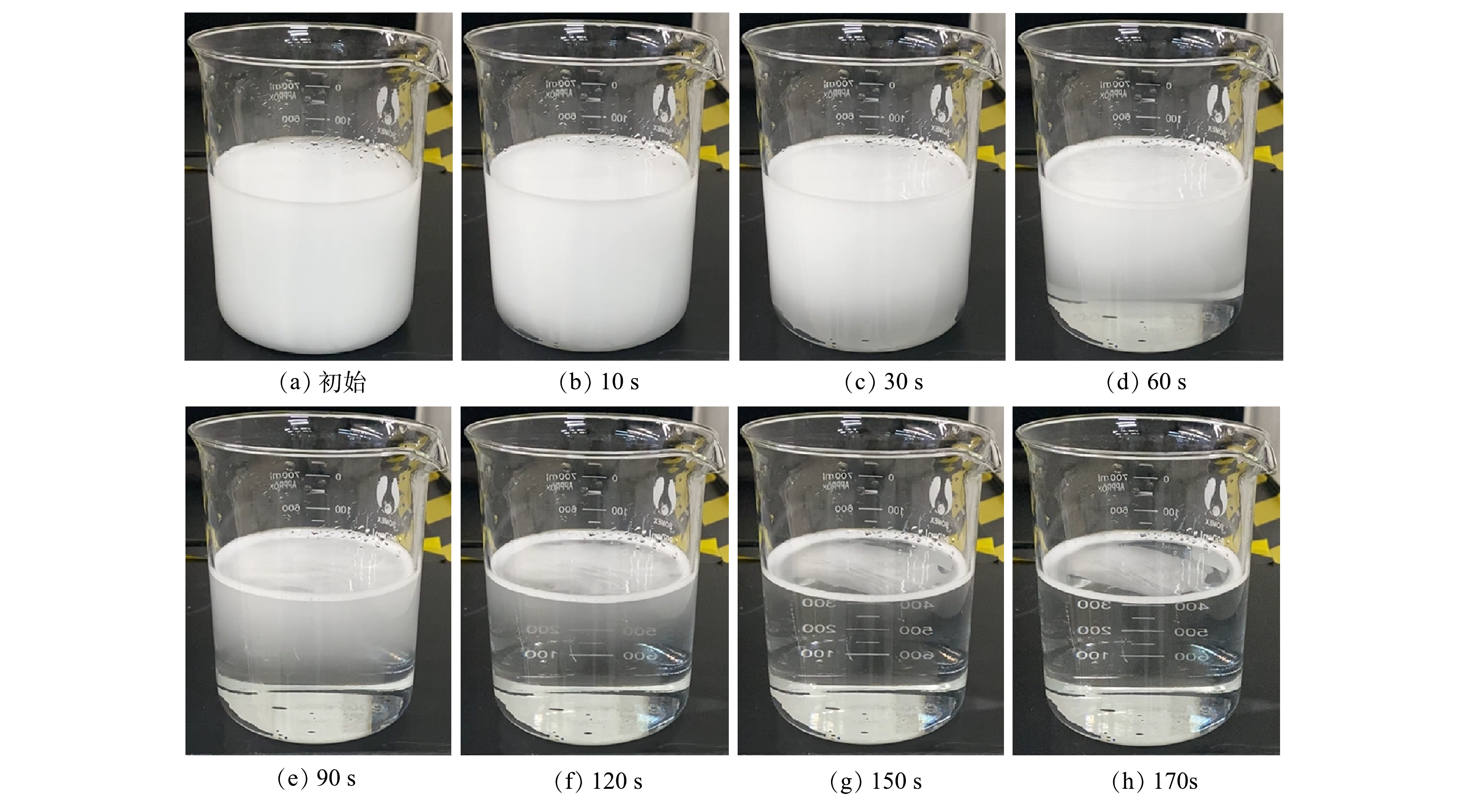
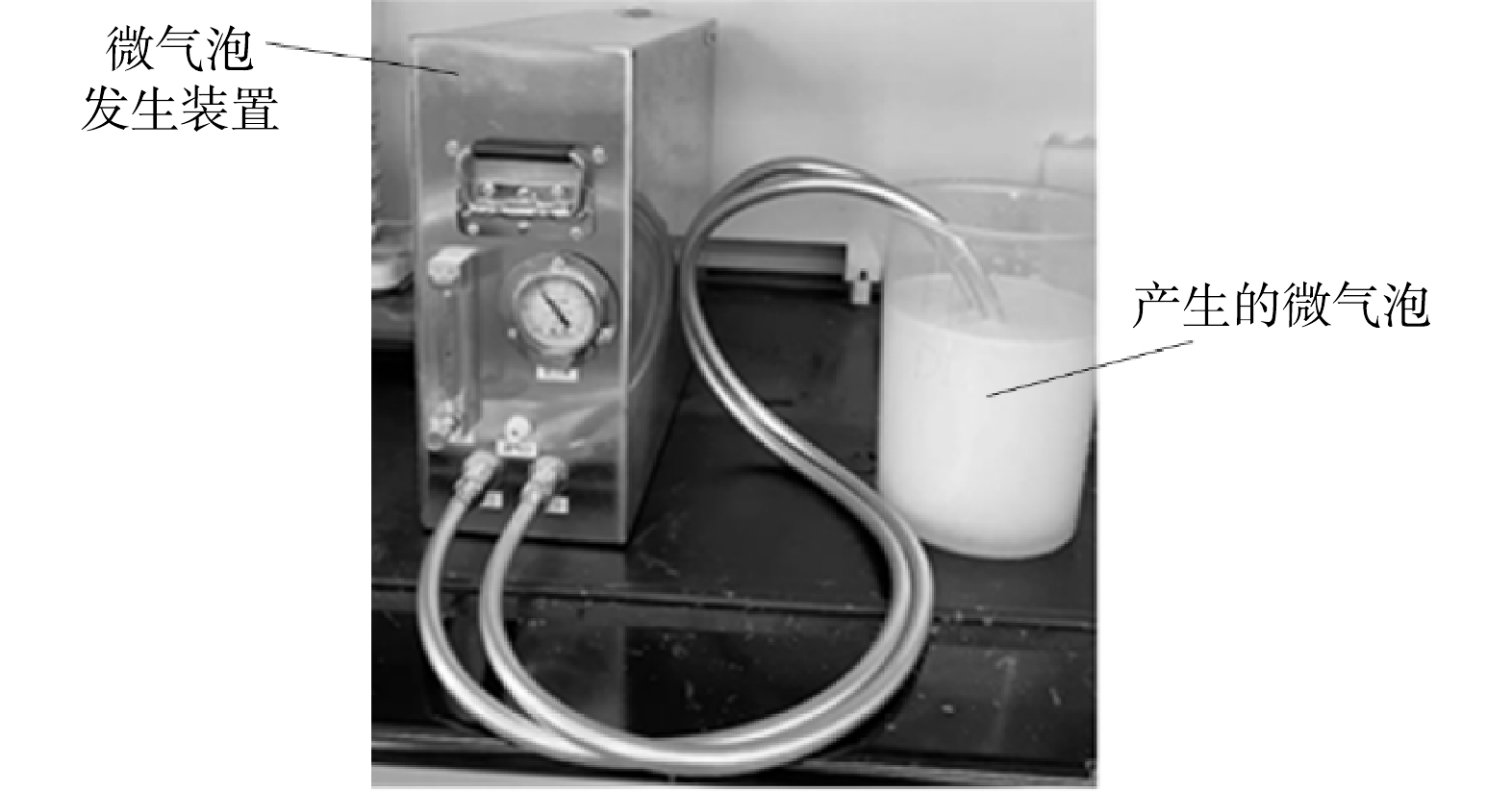
微气泡发生装置如图1所示。微气泡发生装置包括1个增压-释放器和1个射流器,气-液两相流体首先进入加压的容器罐中,然后再通过释放器产生大量的微气泡。微气泡装置外形尺寸(宽×高×深)为160 mm×500 mm×380 mm,功率为50 W,气泡水出水流量为200 L·h−1,进气流量为20~160 mL·min−1,不同进气量对应的出口压力见表1。气含率根据床层塌陷法进行估算,微气泡发生器出口压力是指微气泡装置中经过释放器产生微气泡的压力降。从微气泡发生装置产生的的气泡水呈乳白色,在2 min左右会变清澈,意味着微米级的气泡在2 min之内会彻底消失,实验情况见图2。实验条件为室温20 ℃,常压。
采用马尔文MS3000对微气泡粒径分布进行表征。马尔文MS3000的测试原理是激光衍射法,这种方法适合测量亚微米到几百微米的样品颗粒。在测试过程中,将微气泡发生装置产生的气泡水引入到MS3000的测试区样品池,形成一个稳定的动态循环流动的系统,实现在线测试粒径分布的目的。MS3000配套样品槽最大流速为2.0 L·min−1,样品槽容积为600 mL,样品装样体积要求为400 mL,测量时间可以调节。红光光源为Max. 4 mW He-Ne, 波长为632.8 nm;蓝光光源为Nominal 10 mW LED, 波长为470 nm。使用仪器时,打开马尔文MS3000电源,使仪器初始化,自动对光完成后,进入背景测试阶段;然后仪器会提示加入样品,再调节分散剂阀门开度,调至合适的遮光度范围内,进行测试。
-
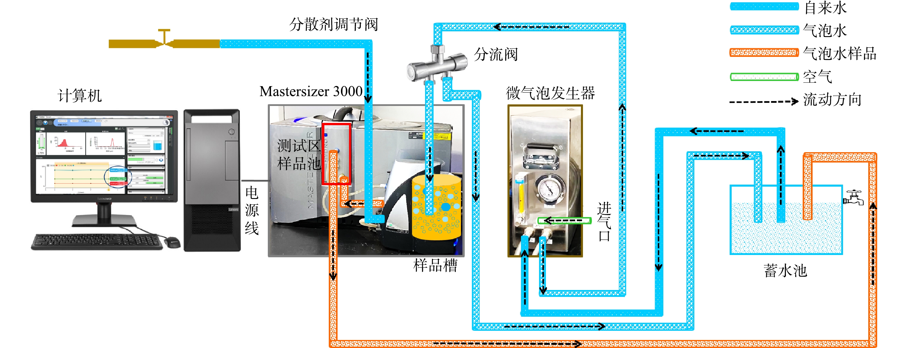
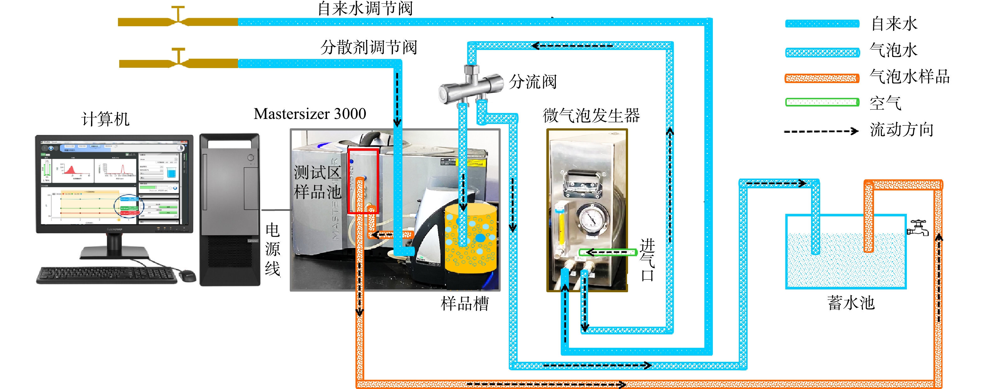
微气泡测试系统包括在线测试平台1和在线测试平台2,其流程如图3和图4所示。设定气相流量,先打开自来水调节阀,流经微气泡发生器,产生200 L·h−1气泡水,流至分流阀;调节分流阀开度,分流阀一路流入样品槽,一路流至蓄水池;与此同时,打开分散剂调节阀;分流阀中的气泡水在样品槽中快速与分散剂进行混合,形成测试样品,然后流到测试区的样品池;测试完毕后再流至蓄水池,这样得到一个循环系统,可以实时得到气泡水中气泡的粒径分布。平台1(图3)与平台2(图4)的差别在于进入微气泡发生装置的液相不同。平台1的液相采用新鲜的自来水,而平台2的液相采用的是蓄水池中储存的循环水。
本研究搭建的在线系统可以准确测定和分辨不同水质来源(循环水和新鲜自来水)产生的气泡尺寸的差异,可将其推广应用到不同水体的深度处理中,如工业污水、生活污水、制药厂污水的实时监测,同时亦可依据监测结果及时给出调节或者优化系统的策略。本系统也可以监测不同操作条件下气泡尺寸的变化规律,为水处理、臭氧催化、气液相反应的过程强化提供数据支撑。
-
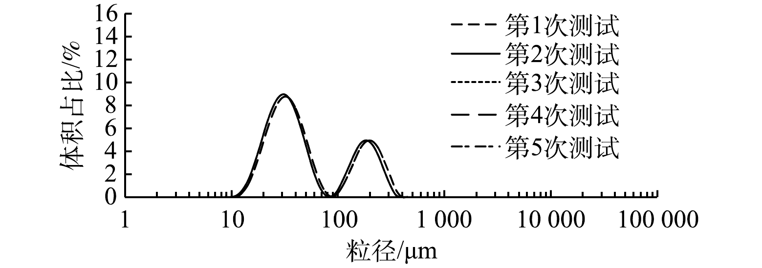
在测量过程中,采用微气泡测试平台2(图4)。液相为循环水,设定气相流量为60 mL·min−1,按照1.2中所述的测试步骤,可以在计算机上看到气泡粒径的实时粒径分布。然后取其中5组数据进行整理,结果见图5。由图5可以看出,5组数据的结果基本一致,取其平均值代表所在气相流量下的粒径分布。在后续实验中,数据处理均取5次测试结果的平均值。
-
如图6所示,当进气量为60 mL·min−1时,在气泡水流量稳定的条件下,考察遮光率对微气泡粒径的影响。通常情况下,如果样品颗粒比较小,那么遮光率范围小一些比较好,遮光率为5%~10% 时可达到合适的信噪比;如果颗粒比较大,遮光率可以调节到 5%~12%;如果样品分布很宽,遮光率为15%~20% 时有利于取样。在含有微气泡的液相体系中,气泡数目过多会造成多重衍射,使得测量结果失真,故以自来水作为分散剂来稀释微气泡的浓度,使其遮光度保持在5%~15%,得到的测试结果更可靠。微气泡粒径为10~100 μm,遮光率的变化对粒径的测试结果没有任何影响;但是粒径超过100 μm,遮光率为9.69%和遮光率为13.79%的粒度分布结果几乎相同,同时比遮光率为5%对应的粒径大。这主要是由于遮光率高,气泡相对比较密集,发生碰撞而聚并的频率较高,故导致大气泡的体积占比增加。真实体系中的气泡数目较多,不可避免地会发生碰撞,因此,后续实验中均设置遮光率为10%左右。
-
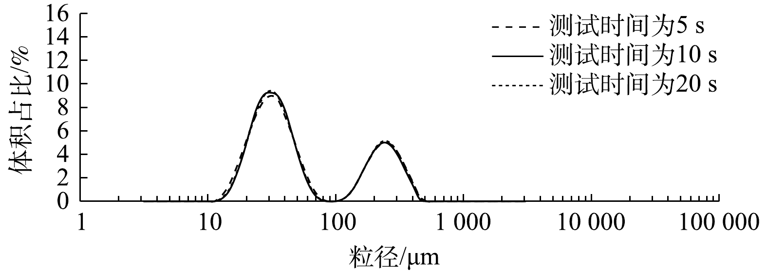
如图7所示,在微气泡粒径为10~100 μm时,进入测试区的管路越短,对应的微气泡体积占比越高;而当粒径为100~1 000 μm时,进入测试区的管路越长,微气泡体积占比相对越高。造成这种现象的主要原因是气泡聚并现象发生在测试系统的流动过程中,停留时间的延长会增加气泡聚并的频率,管路越短,得到的小气泡越多;管路越长,大量气泡发生聚并从而导致大气泡体量增加。为了最大程度减小气泡聚并对检测过程产生的影响, 并最大限度地将样品池与样品混合槽有效连接起来,在后续实验中,进入样品池的管长均设置为6 cm。由图8可以看出,随着测试时间的延长(5、10和20 s),测试结果完全一致,故后续的测试时间均选择为10 s。
-
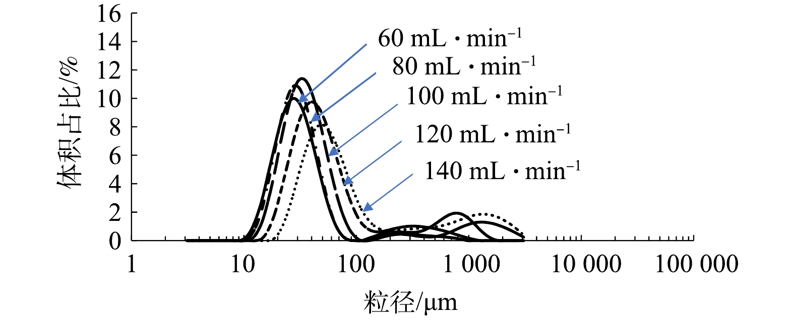
在测试过程中,采用测试平台1,遮光率为10%,进样距离为6 cm, 测试时间为10 s,每个样品测试取平均值,改变进气量,得到相应的微气泡粒径分布,结果见图9。可以看出,当微气泡发生器的液相为蓄水池中的循环水时,粒径分布呈现典型的双峰分布,粒径(d0)为10~100 μm的微气泡体积占比高于粒径为100~1000 μm的体积占比。
由表2可以看出,当引入微气泡发生器的液相为循环水时(即采用测试平台2),粒径d0<10 μm的气泡不存在;粒径为30~60 μm的微气泡体积占比最高,其次是粒径d0>150 μm的气泡。当进气量为60、80、100、120和140 mL·min−1时,测得的微气泡表面积平均直径(Ds)分别为42.5、55.3、51.7、56.3和65.2 μm;测得的微气泡体积平均直径(Dv)分别为90.9、148、132、146和181 μm。随着进气量的增加,微气泡的表面积平均直径(Ds)和体积平均直径(Dv)会逐步增加,说明微气泡尺寸越来越大。这是因为微气泡发生装置主要采用的是液相剪切,此时的液相采用的是富含气泡的循环水,剪切力不及纯液相,导致气泡尺寸逐步增加,同时小粒径的气泡数量降低。
采用测试平台2进行测试,此时微气泡发生装置的液相为新鲜自来水,不同进气量对应微气泡粒径的体积占比结果见表3。可以看出,进气量较小(40~80 mL·min−1)时,随着进气量的增加,粒径d0<10 μm的气泡越来越少,体积占比由0.02%减至0.000 1%;d0>150 μm的气泡体积占比越来越低,体积占比由44.37%降至15.81%;粒径为10~100 μm的微气泡体积占比由54.99%增至84.13%。如表3所示,当进气量为40 mL·min−1时,粒径为10~30 μm和30~60 μm 的微气泡体积占比最高分别为25.93%和24.40%;当进气量为60 mL·min−1时,10~30 μm和30~60 μm 的微气泡体积占比最高分别为41.15%和37.24%;当进气量为80 mL·min−1时,30~60 μm和10~30 μm 的微气泡体积占比最高分别为41.35%和39.72%。
进气量较高(100~140 mL·min−1)时,微气泡的体积占比有差异。微气泡粒径小或者较大时,不同进气量对应的体积占比会有所不同,当进气量为100 mL·min−1时,粒径d0<10 μm的微气泡数目越来越少,对应的体积占比为0.000 06%;当进气量为120 mL·min−1和140 mL·min−1时,粒径d0<10 μm的微气泡不存在;粒径d0>150 μm的微气泡体积占比越来越高,体积占比由4.47%增至28.12%;粒径为10~100 μm的微气泡体积占比由95.5%降至69.13%。微气泡粒径为10~60 μm时,不同进气量对应的体积占比也不同,当进气量为100 mL·min−1时,粒径为30~60 μm和10~30 μm 的微气泡体积占比最高,分别为52.5%和32.65%;当进气量为120 mL·min−1时,粒径为30~60 μm和60~100 μm 的微气泡体积占比最高,分别为48.61%和19.63%;当进气量为140 mL·min−1时,粒径为30~60 μm和60~100 μm 的体积占比最高,分别为36.74%和23.41%。
由图10可以看出,与微气泡装置进水为循环水(含微气泡)的双峰分布情形不同,当微气泡发生装置进水为新鲜自来水时,微气泡粒径呈现显著单峰分布。在实验区间(40~140 mL·min−1)内,粒径为10~100 μm的小气泡体积占比最高。比较而言,进气量小于100 mL·min−1时,粒径为10~60 μm的小气泡体积占比较大;进气量大于100 mL·min−1时,粒径为3~100 μm的小气泡体积占比较大。由于溶气-释气法的原理是依靠空化、剪切等多种作用使得饱和的气体从溶液中快速释放,气液相流出总量是固定的,当水源为新鲜自来水时,液相剪切作用更为显著,故小气泡体量大,呈单峰分布;当水源为循环气泡水时,液相中含有部分气泡,增加了测试过程中气泡聚并概率,故会出现大气泡的峰形,而呈现出双峰分布。由图11可以看出,随着进气量的增加(60~140 mL·min−1),粒径分布曲线向右平移,意味着最大体积占比的粒径逐步增大,同时,对应的体积占比逐步降低。这是由于微气泡发生装置是依靠空化、剪切等多种作用使得饱和的气体从溶液中快速释放,气液相流出总量固定为200 L·h−1,较少进气量时,气相含量越低,液相含量越高,液相的剪切作用愈加显著,故产生的小气泡会较多;但是随着进气量的增加,剪切作用逐步减弱,故产生的小气泡总体体积含量降低。
由图10和图11可以看出,溶气-释气法产生的微细气泡粒径为10~150 μm,这与已有研究[30]中的粒径测试结果吻合。其拖尾部分的粒径为100~1 000 μm。这是由于微米级的气泡流经样品池的过程需要一定的停留时间,随着时间的推移,气泡会发生一定概率的聚并,产生大的气泡,从而造成拖尾现象。另外,大气泡的出现也与流动体系的稳定性有关,如进气量为40 mL·min−1时,其流动不稳定造成大气泡数量远远超过其他进气量(60~140 mL·min−1)的情况。
-
1)基于衍射法搭建的微气泡尺寸分布在线测量平台,测量精度为±0.6%,具有重复性好、精度高、可控性强、操作简单等优点。同时,该测量方法得到的气泡尺寸分布与溶气-释气法测定的数据非常吻合。
2)随着进气量的增加(60~140 mL·min−1),气泡尺寸逐渐增大,其对应的体积比逐渐减小。溶气-释气法通过空化和剪切等各种作用从溶液中产生微气泡,一旦气体和液体流出的总量是固定的,气相流量越高,意味着液相越少。当液相入口为新鲜自来水时,剪切作用更显著,小气泡体积大,形成单峰分布曲线;当液相入口为循环水时,由于实验过程中气泡聚并的概率增加,会出现大气泡的峰值,从而得到双峰分布。
3)气泡尺寸分布曲线中的拖尾现象是由于气泡聚并频繁产生的大气泡引起的。此外,大气泡的出现也与流动系统的稳定性有关。当进气口为40 mL·min−1时,流动不稳定导致大气泡的数量远远超过其他进气口(60~140 mL·min−1)的情况。因此,保证流动系统的稳定性也是测试可靠的基础和前提。此方法通过实时监测气泡的尺寸变化情况,实现整个系统的有效调控,未来有望在污水处理、水体增氧、臭氧催化反应和气液相化学反应等领域得到推广及应用。
在线实时监测微气泡尺寸系统的构建及效果分析
Construction and effect analysis of a test system for online real-time monitoring the microbubble size
-
摘要: 为在线监测污水处理、水体增氧和气液相化学反应过程中的气泡粒径的实时变化情况,构建了一种在线测试微气泡群的测试系统,并进行气泡粒径的实时监测;将微细气泡发生装置产生的气泡水引入到粒度分析仪的测试区样品池,形成一个稳定的动态循环流动的系统;通过调节分流阀和分散剂阀同时实现样品的均匀混合和在线取样,再将样品输送至样品池进行快速检测,实现气泡尺寸的在线实时监测。结果表明:当遮光率为10%,从样品槽混合好的样品到样品池的距离为6 cm,测试时间为10 s时,可获得测试微细气泡粒径的最佳条件,精度为±6%;溶气-释气法产生的微细气泡粒径为10~150 μm;随着进气量的增加,气泡的尺寸逐渐增加,其对应的体积比逐渐较小;气泡的粒径还会受到液相水样的影响,当液相为循环水时,气泡粒径呈双峰分布;当液相为新鲜自来水时,气泡粒径呈单峰分布。微气泡尺寸在线测试平台具有具有重复性好、精度高、可控性强、操作简单等特点。本研究结果可为微气泡在污水处理、水体增氧和气液相反应等场合的应用提供参考。Abstract: In order to online monitor the real-time variation of bubble size in sewage treatment, water oxygenation and gas-liquid chemical reaction, a test system for online testing of micro-bubble groups was constructed to realize the real-time monitoring of bubble size. The bubble water produced by the micro-bubble generator was introduced into the sample cell of the particle size analyzer in the test area and a stable dynamic circulating flow system was formed. By adjusting the diverter valve and the dispersant valve, the uniform mixing and online sampling could be realized at the same time. Then the sample was transported to the sample cell for rapid detection which could realize online real-time monitoring of bubble size. The tested results with an accuracy of ±6% showed that the optimal conditions for testing the particle size of micro-bubble were following: the shading rate was 10%, and the distance from the mixed sample in the sample tank to the sample cell was 6 cm, and the test time was 10 s. The particle size of the micro-bubble produced by the dissolved gas-release method was 10~150 μm, which was in good agreement with the literature results. Simultaneously, with the increase of air inlet, the size of the bubble gradually increased, and its corresponding volume ratio gradually decreased. The bubble size was also affected by the liquid water inlet. The bubble size displayed a bimodal distribution with the liquid phase of circulating water, while it displayed a unimodal distribution with the liquid phase of fresh tap water. The microbubble size online test platform presented the characteristics of good repeatability, high precision, strong controllability and simple operation, the results of this study can provide a reference for the application of microbubbles in sewage treatment, water oxygenation and gas-liquid phase reactions.
-

-
表 1 微气泡表征实验的实验条件及估算的气含率
Table 1. Experimental conditions and estimated gas holdup in this work
样品序号 进气量/
(mL·min−1)气含率 /% 微气泡发生器
出口压力/MPa1 40 4.10 0.41 2 60 3.80 0.40 3 80 3.74 0.38 4 100 3.70 0.36 5 120 2.99 0.30 6 140 2.31 0.20 表 2 循环水引入微气泡发生器时粒径的体积占比
Table 2. Volume proportion of bubble size with the liquid phase inlet of circulating water
粒径/μm 微气泡体积占比/% 进气量
40 mL·min−1进气量
60 mL·min−1进气量
80 mL·min−1进气量
100 mL·min−1进气量
120 mL·min−1进气量
140 mL·min−1<10 0 0 0 0 0 0 10 ~ 30 17.01 26.39 15.43 20.03 12.48 8.55 30 ~ 60 40.99 38.82 38.58 41.72 43.24 39.04 60 ~100 6.11 4.53 5.52 5.35 6.72 7.78 100 ~ 120 0.003 0.74 0.003 0.04 0.002 0.005 120 ~ 150 0.59 3.48 0.53 0.97 0.36 0.66 >150 35.30 26.04 39.93 31.90 37.20 43.96 表 3 新鲜自来水引入微气泡发生器时微气泡的体积分布
Table 3. Surface area/volume diameter of microbubble with the liquid phase inlet of fresh tap water
粒径/μm 微气泡体积占比 /% 进气量
40 mL·min−1进气量
60 mL·min−1进气量
80 mL·min−1进气量
100 mL·min−1进气量
120 mL·min−1进气量
140 mL·min−1<10 0.02 0.01 0.001 0.000 06 0 0 10 ~ 30 25.93 41.15 39.72 32.56 16.29 5.05 30 ~ 60 24.40 37.24 41.35 52.50 48.61 36.74 60 ~100 4.18 2.98 3.06 10.13 19.63 23.41 100 ~ 120 0.48 0.002 0.000 05 0.22 2.39 3.93 120 ~ 150 0.62 0.25 0.05 0.03 1.55 2.75 >150 44.37 18.37 15.81 4.47 11.53 28.12 -
[1] 李兆军, 杜浩. 我国微泡技术发展综述[J]. 过程工程学报, 2017, 17(4): 655-663. doi: 10.12034/j.issn.1009-606X.216346 [2] TESAŘ V. Microbubble smallness limited by conjunctions[J]. Chemical Engineering Journal, 2013, 231: 526-536. doi: 10.1016/j.cej.2013.06.051 [3] 张静, 杨旭, 康帆, 等. 微气泡催化臭氧化深度处理制药废水的效果及DOM组分特性的变化[J]. 环境工程学报, 2022, 16(5): 1469-1479. doi: 10.12030/j.cjee.202201172 [4] 刘春, 高立涛, 张静, 等. 微气泡臭氧化强化吸收-氧化处理高浓度乙酸乙酯气体[J]. 环境工程学报, 2021, 15(5): 1616-1624. doi: 10.12030/j.cjee.202008028 [5] 张静, 钱泽朋, 刘春, 等. 微气泡催化臭氧化酸性大红3R的性能及机理[J]. 环境工程学报, 2021, 15(4): 1199-1208. doi: 10.12030/j.cjee.202009054 [6] ATKINSON A J, APUL O G, SCHNEIDER O, et al. Nanobubble technologies offer opportunities to improve water treatment[J]. Accounts of Chemical Research, 2019, 52(5): 1196-1205. doi: 10.1021/acs.accounts.8b00606 [7] TESAŘ V. Microbubble generation by fluidics[J]. Part II:Bubble formation mechanism[C]//Institute of Thermomechanics AS CR. Colloquium FLUID DYNAMICS 2012. Prague, 2012: 1-20. [8] GARSTECKI P, FUERSTMAN M J, STONE H A, et al. Formation of droplets and bubbles in a microfluidic T-junction-scaling and mechanism of break-up[J]. Lab on a Chip, 2006, 6(3): 437-446. doi: 10.1039/b510841a [9] 张志炳, 微界面传质强化技术 [M]. 北京: 化学工业出版社, 2020. [10] 梁倩卿, 春江, 王凯, 等. 弯曲型微通道吸收CO2/N2混合气的传质性能[J]. 高校化学工程学报, 2017, 31(4): 784-793. doi: 10.3969/j.issn.1003-9015.2017.04.005 [11] 尧超群, 陈光文, 袁权. 微通道内气-液两相传质过程行为及其应用[J]. 化工学报, 2019, 70(10): 3635-3644. [12] 尧超群, 乐军, 赵玉潮, 等. 微通道内气-液弹状流动及传质特性研究进展[J]. 化工学报, 2015, 66(8): 2759-2766. [13] 梁倩卿, 马学虎, 王凯, 等. 矩形截面弯曲型微通道气液两相Taylor流压降的研究[J]. 化工学报, 2019, 70(4): 1272-1281. [14] AZIZI S, YADAV A, LAU Y M, et al. Hydrodynamic correlations for bubble columns from complementary UXCT and RPT measurements in identical geometries and conditions[J]. Chemical Engineering Science, 2019, 208: 115099. doi: 10.1016/j.ces.2019.07.017 [15] VAN STEIJN V, KREUTZER M T, KLEIJN C R. μ-PIV study of the formation of segmented flow in microfluidic T-junctions[J], Chemical Engineering Science, 2007, 62(24): 7505-7514. [16] YAO C Q, DONG Z Y, ZHANG Y C, et al. On the leakage flow around gas bubbles in slug flow in a microchannel[J]. AIChE Journal, 2015, 61(11): 3964-3972. doi: 10.1002/aic.14895 [17] SHARAF S, ZEDNIKOVA M, RUZICKA M C, et al. Global and local hydrodynamics of bubble columns: Effect of gas distributor[J]. Chemical Engineering Journal, 2016, 288: 489-504. doi: 10.1016/j.cej.2015.11.106 [18] MÖLLER F, SEILER T, LAU Y M, et al. Performance comparison between different sparger plate orifice patterns: Hydrodynamic investigation using ultrafast X-ray tomography[J]. Chemical Engineering Journal, 2017, 316: 857-871. doi: 10.1016/j.cej.2017.01.114 [19] MUDDE R F, GROEN J S, VAN DEN AKKER H E A. Liquid velocity field in a bubble column: (LDA) experiments[J]. Chemical Engineering Science, 1997, 52(21/22): 4217-4224. [20] BECKER S, DE BIE H, SWEENEY J. Dynamic flow behaviour in bubble columns[J]. Chemical Engineering Science, 1999, 54(21): 4929-4935. doi: 10.1016/S0009-2509(99)00214-6 [21] BHOLE M R, ROY S, JOSHI J B. Laser Doppler anemometer measurements in bubble column: Effect of sparger[J]. Industrial & Engineering Chemistry Research, 2006, 45(26): 9201-9207. [22] SATHE M, JOSHI J, EVANS G. Characterization of turbulence in rectangular bubble column[J]. Chemical Engineering Science, 2013, 100: 52-68. doi: 10.1016/j.ces.2013.01.004 [23] SUJATHA K T, MEEUSEN B G J, KUIPERS J A M, et al. Experimental studies of bubbly flow in a pseudo-2D micro-structured bubble column reactor using digital image analysis[J]. Chemical Engineering Science, 2015, 130: 18-30. doi: 10.1016/j.ces.2015.02.029 [24] 李天成, 辛峰. 电导法测定气-液鼓泡床反应器内的气泡直径[J]. 天津大学学报, 2002, 35(2): 231-234. [25] 李希, 李兆奇, 管小平, 等. 气液鼓泡塔流体力学研究进展[J]. 高校化学工程学报, 2015, 29(4): 766-779. [26] WALKE S M, SATHE V S. Study on the gas holdup of triangular pitch and square pitch sparger geometry in bubble column[J]. International Journal of Fluid Mechanics Research, 2012, 39(1): 85-97. doi: 10.1615/InterJFluidMechRes.v39.i1.60 [27] KIAMBI S L, DUQUENNE A-M, DUPONT J B, et al. Measurements of bubble characteristics: Comparison between double optical probe and imaging[J]. Canadian Journal of Chemical Engineering, 2003, 81(3/4): 764-770. [28] GUET S, FORTUNATI R V, MUDDE R F, et al. Bubble velocity and size measurement with a four-point optical fiber probe[J]. Particle & Particle Systems Characterization, 2003, 20(3): 219-230. [29] MIZUSHIMA Y, SAKAMOTO A, SAITO T, et al. Measurement technique of bubble velocity and diameter in a bubble column via single-tip optical-fiber probing with judgment of the pierced position and angle[J]. Chemical Engineering Science, 2013, 100: 98-104. doi: 10.1016/j.ces.2013.01.046 [30] TERASAKA K, AI H, NISHINO T, et al. Development of microbubble aerator for waste water treatment using aerobic activated sludge[J]. Chemical Engineering Science, 2011, 66(14): 3172-3179. doi: 10.1016/j.ces.2011.02.043 -


 下载:
下载:
